The quantum scientist’s guide to filtering
The HERD application note as a page.
- <0.15 dB
- insertion loss, DC–8 GHz typical
- >65 dB
- stopband attenuation, 70–120 GHz typical
- 70–145 GHz
- stopband, minimum
HERD-2 datasheet
01HERD Filters
HERD filters are high-performance lowpass filter with < 0.1 dB insertion loss in the 0–12 GHz band and over 50 dB of attenuation in a wide stopband starting at 60 GHz and extending to 145 GHz (measured) and above. This unparalleled performance is achieved thanks to the patented High-Energy Radiation Drain (HERD) technology, which directs high-frequency radiation away from the main propagating path of the filter and into an absorptive region. By contrast, low-frequency radiation never enters the absorptive region and propagates undisturbed across the filter.
02Applications in Superconducting Quantum Computing
Quantum processing units (QPUs) based on superconductors need to be cooled down to very low temperatures (<10 mK) and communicate to classical electronics via electromagnetic pulses in the 4–8 GHz band. At the same time, QPUs are extremely sensitive to radiation at frequencies above a certain cutoff 2Δ/ℏ, where Δ is the superconducting energy gap and ℏ is the reduced Planck constant. Radiation exceeding this frequency is referred to as Cooper-pair breaking radiation and can cause partial disruption of superconductivity, which is very detrimental for the performance of the QPU.
For common materials and film thicknesses used in superconducting quantum computing, the cutoff is in the range of tens of GHz up to a few THz. For example, in Al, the most common material used to realize Josephson junctions – the core element of superconducting QPUs – the cutoff frequency is around 80 GHz. To protect QPUs, various filtering strategies have been implemented, including absorptive filters based on magnetically loaded dielectrics or copper powder (on input lines to the QPU), and ferrite circulators (on output lines from the QPU to a signal amplification stage). Thanks to its ultralow loss in the passband, HERD can be integrated in all signal lines connecting the QPU to higher temperature stages, thereby reducing thermal interference and delivering superior performance for the QPU.
03Integrating HERD in a Quantum Computing Setup
QPUs are stored and operated in a cryogenic environment, typically a dilution refrigerator. QPUs are connected to room-temperature electronics via measurement and control lines, serving as inputs to and outputs from the QPU.
Types of Lines
Here are the four most common types of lines to be found in a superconducting quantum computer:
- 1.Readout input lines are used to drive readout resonators to query the state of the qubits. Any residual in-band thermal radiation results in degraded qubit performance via thermal-shot-noise-induced dephasing (even at the single-photon level, ~10−24 W/Hz), so these lines are the most heavily filtered. They work in the 4–8 GHz bandwidth.
- 2.Charge lines are used to drive XY rotations on qubits. They are typically weakly coupled to the qubits to prevent the qubits from decaying into them, for this reason, they need to handle more power but can also tolerate a higher thermal background. They also work in the 4–8 GHz bandwidth.
- 3.Flux lines are used to drive Z rotations on qubits by changing the current flowing in on-chip superconducting loops. The currents to be carried are of the order of 1 mA. They require a bandwidth from DC up to 1 GHz.
- 4.Readout output lines are used to collect signal from the readout resonators, with a power level in the order of −120 dBm. Losses should be avoided, especially between the QPU output and the first amplifier in the chain. In state-of-the-art setups, the first amplifier in the chain is often a nearly-quantum-limited amplifier operating at the same temperature stage as the QPU; for example, a Josephson Parametric Amplifier (JPA) or a Traveling-Wave Parametric Amplifier. In other setups, the first amplifier is a high-electron mobility transistor (HEMT) amplifier operated at the 4K stage of the dilution refrigerator.
Filtering Strategy
In input lines of type 1–3, various attenuators and filters are deployed to reduce thermal background and protect the QPU from noise and interference. By contrast, output lines carry tiny electromagnetic signals encoding information regarding the state of the quantum bits. These signals are amplified by an amplification chain including one or more cryogenic amplifiers as the first stage, and nonreciprocal components (isolator, circulators) are used to decouple the QPU from the backaction of the noisy amplifiers. Broadband attenuation is a viable strategy for input lines (with constraints related to power handling and heat loads, see Ref. 1 for details), but not for output lines, because it would result in loss of useful signal and as a result worse performance in qubit readout (speed, fidelity). However, the requirement of rejecting high-frequency radiation is common to all types of lines.
04Conventional Absorptive Filters vs HERD
Conventional absorptive filters (for example, those based on Copper powder or magnetically loaded epoxies such as Eccosorb™) can be utilized in charge, flux, and readout input lines. Their attenuation profile (in dB) follows a constant decreasing slope as a function of frequency. However, they have the following limitations:
- Unwanted in-band absorption.
- This makes conventional filters less suitable or completely unsuitable for some applications. For example, in output lines, the use of these filters imposes a tradeoff between in-band absorption and IR rejection. If low in-band absorption is required (for example, to optimize readout speed and fidelity), then IR rejection is lowered correspondingly. They can be deployed in charge lines, but at the expense of a tradeoff related to increased attenuation in both the stopband and the passband. The latter also increases the active load on the coldest stage of the dilution cryostat, which in turn limits the number of qubits that can be controlled given a finite cooling power at that stage.
- Dispersion.
- Because the attenuation is frequency-dependent also in the band of interest, fast pulses are distorted.
- Lack of reliability and reproducibility,
- due to the manufacturing process which often involves filling a hollow enclosure with a mixture of absorptive particles and epoxy.
- Sensitivity to high-magnetic fields,
- in case magnetically loaded epoxies are used.
HERD solves these problems by having:
- Minimal in-band absorption
- < 0.15 dB in passband
- Minimal dispersion
- < 0.1 dB ripples in passband
- High reliability and reproducibility,
- thanks to the manufacturing process based on high-precision machining and to the fact that the absorptive material is separated from the main waveguiding path and variations in its properties do not impact the in-band performance.
- Insensitivity to magnetic fields,
- because no magnetic materials are utilized.
- No DC leakage,
- thanks to the fact that the center conductor is completely isolated from the outer conductor of the coaxial structure.
05Where to Install HERD
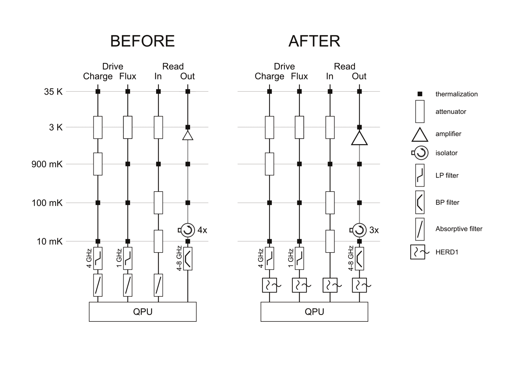
As a result, HERD can be used in all types of lines used to connect the QPU to higher-temperature measurement and control electronics. A simplified wiring diagram of a QPU before and after the installation of HERD is shown in Figure 1. The main benefits are summarized here:
- Aggressive IR filtering of readout lines, with no compromises on the signal transmission in-band. As a result, less circulators/isolators may be needed between the QPU and the first amplifier, which increases the efficiency of the amplification chain.
- In charge and flux lines, no tradeoff between desired isolation in the stopband and unwanted attenuation in the passband. As a result, reduced power load to the base plate.
- In charge and flux lines, no unwanted in-band dispersion due to the absorption profile of the filter. As a result, possibility to drive faster (~ns) pulses with less predistortion.
- In flux lines, no dc/rf current leakage even with currents of the order of tens of mA.
- High reproducibility in the in-band scattering parameters.
06Recommendations How to Install HERD
- Integration.
- We recommend HERD filters to be installed below the base plate of the cryostat and as close as possible to the QPU, to benefit the most from the high-frequency isolation provided by the filter. For best performance, we recommend installing HERD on all lines connected to the QPU.
- Magnetic properties.
- HERD is completely nonmagnetic so it can be installed in close proximity to the QPU. It can also withstand very high magnetic fields, so it can be utilized in setups requiring such fields (for example, QPUs based on spin qubits).
- Matching.
- HERD is very well matched to 50 Ω over a broad 20 GHz bandwidth, so it does not introduce spurious standing waves in measurement and control lines. It can be conveniently combined with reactive filters to narrow the passband and define steep rolloffs.
- Thermalization.
- In the first generation of the filter, HERD-1, thermalizing the outer body of the filter using copper braids has been shown to improve performance. The next-generation filter, HERD-2, obviates the need for this additional step thanks to a change in the materials and manufacturing process. HERD-2 filters (and related products) are well thermalized to the outer body of the connector and have been shown to ensure state-of-the-art QPU performance with no additional thermalization. HERD-2 filters still provide holes for mounting to a bracket for mechanical or thermal support, depending on the needs of the end user.
- HERD and TWPA.
- In setups using TWPA as the first amplifier, we recommend installing a HERD filter as close as possible to the device under test, before the first component in the TWPA solution. This positioning ensures the best rejection of IR radiation coming, for example, from the TWPA pump line. The impedance of HERD filters is very close to 50 Ω up to 12 GHz in all HERD filters and up to 20 GHz in the HERD-1 and HERD-2 models. As a result, the impedance matching of signals, idlers, and pump in the TWPA is not adversely affected by the installation of the HERD filter.
07Validation
To verify that HERD improves the performance of your quantum computing setup, we suggest the following experiments:
- Measure quasiparticle tunneling rates across a Josephson junction, for example, by using a charge-sensitive transmon qubit. If the tunneling rates are limited by quasiparticle generation or photon-assisted tunneling due to high-frequency radiation in the control line, you will see an improvement after installing HERD. To observe an improvement, an IR-tight sample enclosure is typically required.
- Measure coherence times and thermal population of a superconducting qubit with and without HERD installed.
Examples from the Scientific Community
The group of M. Devoret (Yale University) has explicitly demonstrated a reduction in the quasiparticle tunneling rate in charge-sensitive transmons from 10 Hz to below 1 Hz using HERD-1 and HERD-2 filters, consistently across multiple experiments. Using HERD-2 filters, the group of A. Houck has measured coherence times in excess of 1 ms for 2D transmon qubits. The same group has also measured that the temperature of a fluxonium qubit follows that of the mixing chamber all the way down to the base temperature of 15 mK, using a combination of filters that includes the HERD-1 filter.
08Comparison between HERD and Other Microwave Components
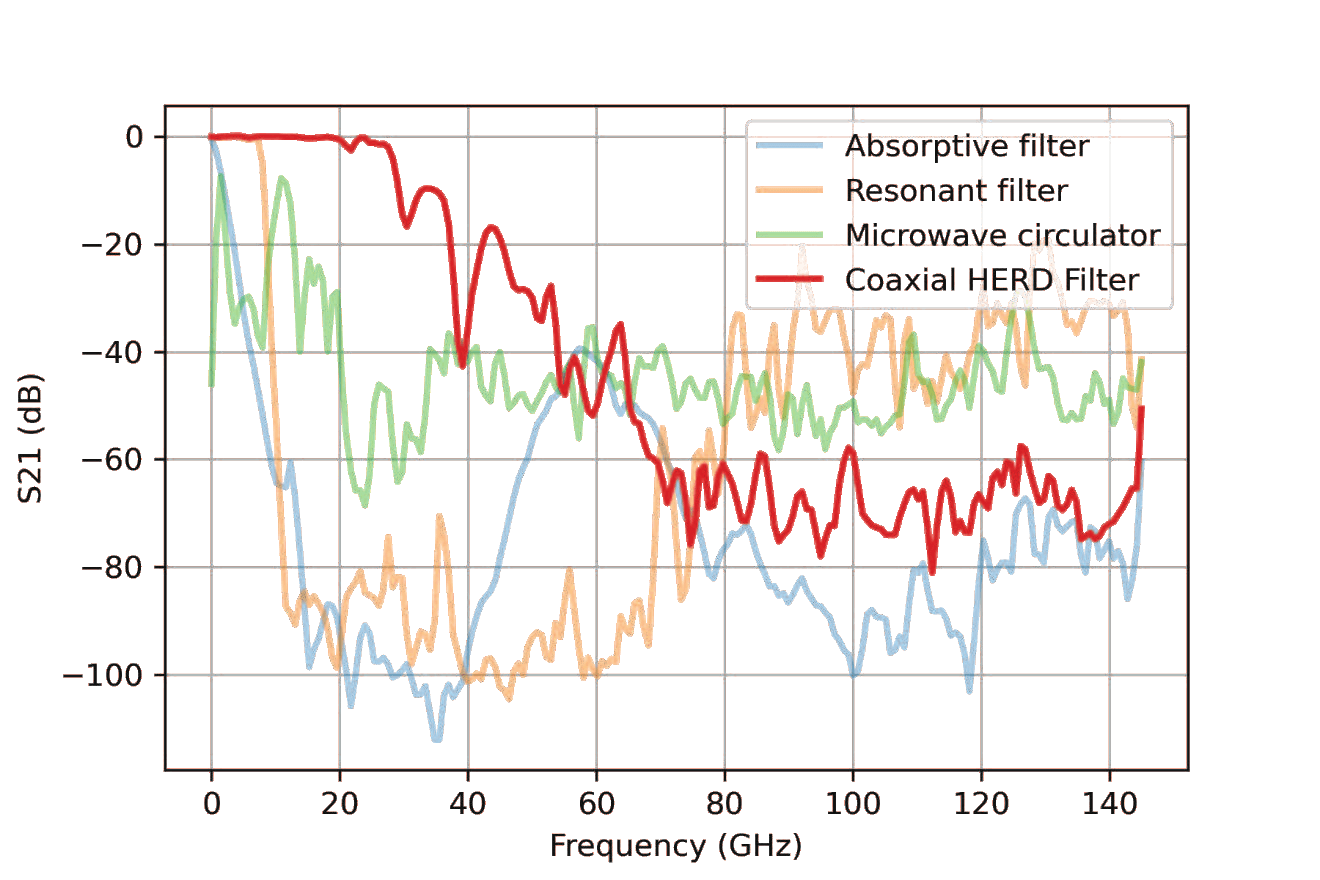
The plot below shows the scattering parameters of various microwave components, measured at room temperature from DC up to 145 GHz: (blue) an in-house-made absorptive filter, (orange) a microwave circulator, (green) a commercial low-pass filter based on cascaded LC sections, and (red) an early prototype of the HERD-1 filter. The absorptive filter has significant in-band loss. The circulator has an intermediate performance. The low-pass filter performs very well in the passband and has a steep rolloff, but it leaks at high frequencies. Finally, HERD combines optimal in-band performance with around 60 dB isolation in the high-frequency range.
09References
- 1.Krinner, S. et al. Engineering cryogenic setups for 100-qubit scale superconducting circuit systems. EPJ Quantum Technology 6, 2 (2019).
A Selection of Research Papers Using HERD Filters
- Original paper describing HERD technology.
- Rehammar, R. & Gasparinetti, S. Low-Pass Filter With Ultrawide Stopband for Quantum Computing Applications. IEEE Transactions on Microwave Theory and Techniques 71, 3075–3080 (2023).
- Group of M. Devoret. Yale University.
- Nho, H. et al. Recovery Dynamics of a Gap-Engineered Transmon after a Quasiparticle Burst. Phys. Rev. Lett. 136, 050601 (2026).
Hazra, S. et al. Benchmarking the Readout of a Superconducting Qubit for Repeated Measurements. Phys. Rev. Lett. 134, 100601 (2025).
Connolly, T. et al. Full characterization of measurement-induced transitions of a superconducting qubit. Preprint at arXiv:2506.05306 (2025). - Group of L. Grünhaupt. PTB, Germany.
- Gaydamachenko, V., Kissling, C. & Grünhaupt, L. rf-SQUID-based traveling-wave parametric amplifier with input saturation power of −84 dBm across more than one octave in bandwidth. Phys. Rev. Applied 23, 064053 (2025).
- Group of A. Houck. Princeton University.
- Bland, M. P. et al. Millisecond lifetimes and coherence times in 2D transmon qubits. Nature 647, 343–348 (2025).
All publications using HERD, with links.